Introduction
While working at Brightpick, I got the chance to become a doctoral student at the Technical University of Košice. Our remote office was right on the university campus, and when my colleague—who was also teaching there—asked if I’d be interested in doing a PhD, I didn’t think twice. I knew there wouldn’t be a better opportunity than this, so I went for it. This project became the heart of my dissertation.
This blog post summarizes my dissertation thesis in a concise way, covering my goals, the process, and the results. If by any chance someone wants to read the full paper, you can find it here: Autonomous Control of UAV in GPS Denied Environment.
The Problem Statement
Flying drones outdoors is pretty straightforward—GPS gives you global position, and you can plan paths easily. But indoors? No GPS signal at all. That’s what we call a GPS-denied environment: enclosed spaces like rooms, corridors, buildings, warehouses, or even disaster zones where satellite signals don’t penetrate.
The challenges pile up fast. You can’t rely on any external reference for position—everything has to come from onboard sensors. Walls and furniture create tight spaces with high collision risk. Drone propellers cause turbulence and vibrations that mess with sensor accuracy. Depth cameras struggle in dark, reflective, or textureless areas (think plain white walls). And you need real-time localization + mapping (SLAM) to know where you are while building a 3D model of the unknown space. One small drift or error, and you’re flying blind—or into a wall.
This is why indoor autonomous drones are still tricky, but super useful for things like inspection, search & rescue, or inventory scanning.
The Big Goals
The project had a clear progression in three stages:
- First, prove I could create a decent 3D map with a manually controlled setup.
- Then, get the drone to navigate autonomously inside a known map.
- Finally, make it fully autonomous—explore and map completely unknown indoor environments on its own.
All of this using affordable hardware, depth cameras for sensing, and open-source tools. The end goal? Show how drones could handle real indoor jobs like building inspections after disasters, warehouse scanning, or monitoring tight spaces where GPS is useless.
The Handheld Scanner
Before risking the drone, I built a handheld 3D scanner as a proof-of-concept. This let me validate the sensors and mapping software without any chance of crashing hardware. The key idea: use mostly the same components that would later go into the drone—the RealSense cameras, Raspberry Pi as mission computer, battery, power monitoring, etc.—so that tuning, debugging, and lessons learned carried straight over. In the end, the majority of these parts were reused on the flying platform, though a couple (like the specific battery voltage) didn’t make the cut.
I took a plain plastic box as the enclosure—nothing fancy, just sturdy enough to hold everything. I mounted the two Intel RealSense cameras from the side, with all the electronics tucked safely inside to protect them during handheld use.
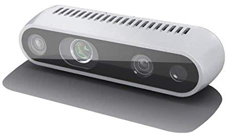 [Intel RealSense D435i: RGB-D depth camera with active IR stereo; Depth FOV: 87° × 58°; Resolution: up to 1280 × 720 @ 90 fps; Built-in IMU for motion data; Global shutter on depth/IR sensors]
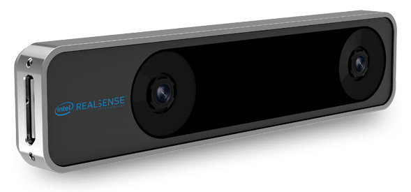 [Intel RealSense T265: Standalone visual-inertial odometry (VIO) tracking camera; Dual fisheye lenses, 163° FOV; Onboard Intel Movidius Myriad 2 VPU; Odometry output up to 200 Hz; Built-in IMU]
The brain was a Raspberry Pi 4 Model B (8GB)—overclocked to 2GHz with a passive heatsink to keep it from throttling during real-time processing. Power came from a 3S LiPo 5000mAh battery (stepped down to 5V via UBEC), which gave me hours of runtime—far more than the drone would get. I wired in an Adafruit INA260 for voltage/current monitoring over I²C, so I could log data and get warnings on low battery.
Connections were straightforward: D435i on USB 2.0, T265 on USB 3.0 for bandwidth. Wi-Fi handled streaming to my laptop for live RViz visualization. RTAB-Map in ROS2 fused the depth data with T265’s reliable pose estimates.
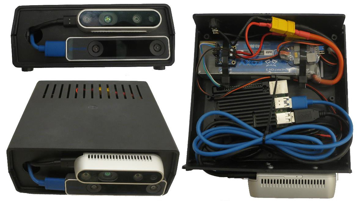 [Handheld scanner with cameras, Raspberry Pi and battery]
I just walked around rooms holding the box like a portable scanner. Point clouds built up nicely in real time, tracking held steady even in bland areas, and loop closure did its job. This phase was a huge win: it proved the sensor fusion worked, gave me solid confidence, and meant most of the hardware/software stack was already battle-tested when I moved to the drone. The reuse saved a ton of rework.
Hardware – What I Actually Flew
The drone I built is a quadrotor—bigger than a typical micro aerial vehicle (MAV), so I just call it a “drone.” Why quadrotor? It can take off vertically, hover steadily, and fly slowly—all must-haves for indoor work where you need precise control in tight spaces.
I didn’t want an off-the-shelf drone; instead, I assembled one from readily available components that met my specs for affordability, reliability, and easy upgrades. Here’s the breakdown of the main parts.
Frame
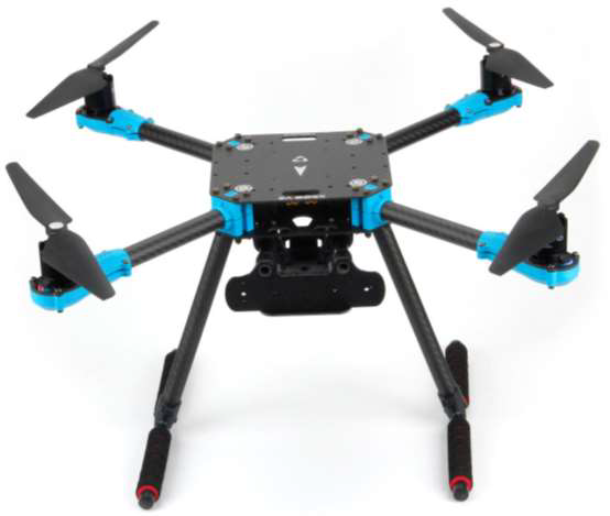
Holybro X500 V2 carbon fiber frame—lightweight, sturdy, and easy to carry. X-shaped design for stability and good payload capacity. Diagonal wheelbase: 500 mm, supports up to 15-inch propellers. Plenty of space for mounting the flight controller, motors, battery, and the included camera mount (which held the RealSense D435i and T265). Carbon fiber kept the weight down while handling the occasional bump better than plastic.
Honestly, it’s a bit too big for really tight indoor spaces—corridors or small rooms might feel cramped with that 500 mm span, and maneuverability suffers. But that’s the trade-off: the size offered a ton of room for experimenting with components, like adding extra sensors, tweaking wiring, or mounting custom parts without everything feeling jammed in. Perfect for a PhD project where I was prototyping and iterating a lot.
 [Holybro X500 V2 frame]
Protection Cage (Prop Guards)
Flying indoors means even a small mistake can smash props into walls, furniture, or the floor—and that usually ends the flight (or worse). I needed prop protection, but nothing off-the-shelf fit the Holybro X500 V2 well.
So I designed a basic protection cage myself in FreeCAD: simple circular guards around each propeller to enclose the blades, connected by lightweight struts that attached to the frame arms using the mounting holes. I reinforced the connections with short carbon fiber rods for a bit more strength without adding much weight. Printed it in durable PETG on my 3D printer. It added roughly 200–300 g overall, which was acceptable given the thrust margin I had.
The cage worked reliably—it took several light bumps during early autonomous tests without any prop damage or major issues. It gave me the confidence to let the drone explore closer to obstacles without constantly hovering in the middle of the room.
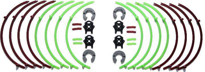 [3D printed parts of protection cage]
 [Design of protection cage in FreeCAD]
Battery
4S LiPo, 4500 mAh capacity—chosen because the motors needed 4S voltage (up from a 3S I already had). Nominal 14.8 V (3.7 V per cell), safe discharge down to ~12 V (3.0 V/cell) to avoid damage, max charge 16.8 V (4.2 V/cell). Good balance: 15–20 minutes flight time depending on payload. I monitored closely to prevent over-discharge risks.
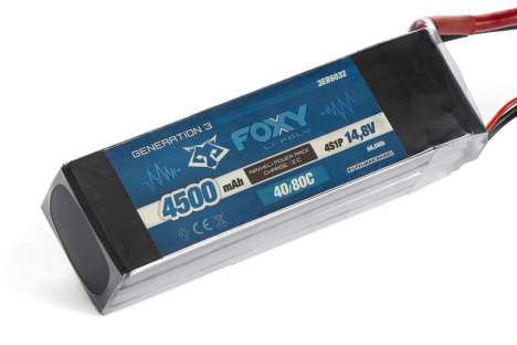 [4S LiPo battery]
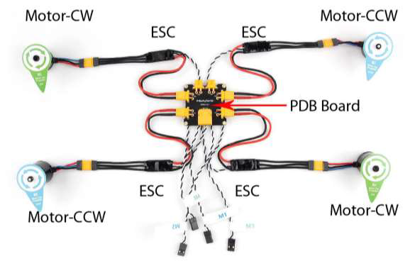
Power Distribution
Holybro PM03D Power Module—measures voltage/current in real time (for low-battery warnings), steps down to 5 V for electronics, and distributes battery voltage to ESCs. Critical for safe operation and not killing the battery prematurely.
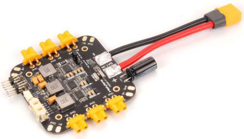 [Power distribution board]
Motors and ESCs
Four AIR 2216 KV920 BLDC motors—efficient, low-resistance for strong thrust. Paired with BLHeli_S 20A ESCs (compact, fast response, motor braking features). Calibrated them to the transmitter for smooth control and to avoid damage.
 [Motors and ESCs]
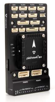
Flight Controller
Pixhawk 6X running PX4 firmware—handles stabilization (IMU-based), motor control, battery monitoring, and emergency actions. Reliable for indoor offboard commands.
 [Pixhawk 6X flight controller]
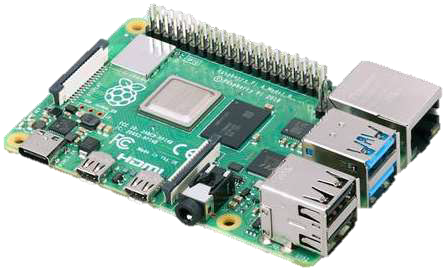
Mission Computer
Raspberry Pi 4 Model B (8GB)—overclocked to 2 GHz with passive heatsink. Tested under full load; temps stayed under 85°C even at max. Prop airflow during flight helped cooling extra. Runs ROS2, processes cameras, does SLAM/navigation/exploration, talks to Pixhawk via Ethernet.
 [Raspberry pi 4 model B]
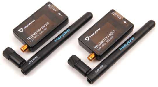
Telemetry Radio
SiK Telemetry Radio V3, 100 mW, 433 MHz—bidirectional for real-time data (position, battery, etc.) and commands from ground station.
 [Pair of telemetry radios]
Depth and Tracking Cameras
Intel RealSense D435i (RGB-D + IMU) and T265 (VIO tracking). Mounted on the kit’s included 3D-printed camera mount for tight integration.
Remote Control
Futaba T6EX transmitter (6 channels) with R617FS receiver—reliable FHSS signal for precise manual overrides and safety.
Assembling of a drone
Putting everything together was fairly straightforward—the Holybro X500 V2 kit comes with clear documentation that covers most of the steps. The frame has pre-drilled holes for bolting parts securely, so assembly felt logical and didn’t require much guesswork.
The center has two stacked base plates. The bottom one mounts the landing legs and two carbon tubes (held in place with rubber and plastic clips). Those tubes support the battery board below and the mission computer mount above. I positioned the Raspberry Pi so its passive heatsink sits directly under the propellers—the downward airflow during flight keeps the overclocked CPU from getting too hot.
On the underside of the bottom plate goes the PM03D power distribution board. The upper plate provides a flat surface for the Pixhawk 6X flight controller, telemetry radio, and RC receiver—all secured with Velcro strips glued to the plate from below. This keeps things removable and tidy without drilling extra holes.
The two plates bolt together and clamp the four drone arms in position. Each arm is a carbon tube with the ESC tucked inside, ending in a motor base plate that holds the motor and propeller. For the prop protection cage, I swapped the stock motor base plates for custom 3D-printed ones with the right mounting points to attach the guards securely.
Wiring followed the kit guide exactly—everything plugs into the correct ports on the Pixhawk, PDB, and other modules. No soldering was needed except for the battery connector. The battery didn’t come with one, and the PDB uses XT60, so I soldered an XT60 plug onto the 4S LiPo wires.
Soldering the XT60 plug to the LiPo was simple, but I had to be careful about short circuits—the battery is sold pre-charged, so any mistake could cause problems. I soldered one wire at a time and made sure the polarity was correct before finishing.
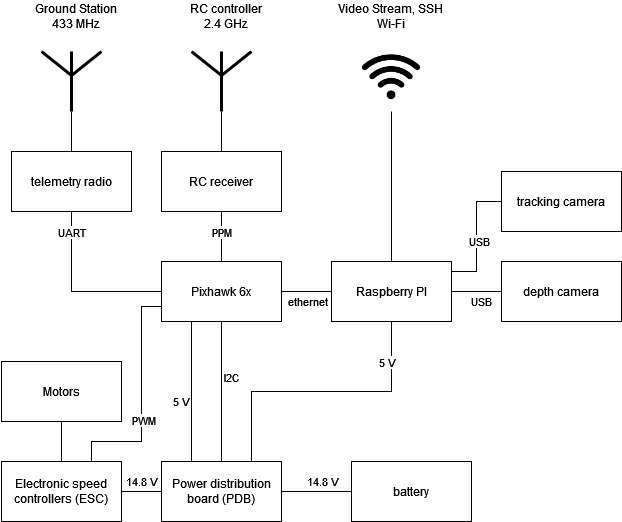
The connections end up like this (in simple terms):
 [Block scheme of all components used for a drone]
- Battery supplies 14.8 V to the PDB.
- PDB powers the motors directly through the ESCs and steps down to 5 V for the flight controller and Raspberry Pi.
- PDB feeds battery voltage and current data to the Pixhawk via I²C for real-time monitoring.
- Pixhawk sends PWM signals to the ESCs to control motor speeds precisely.
- Pixhawk connects to the telemetry radio via UART for 433 MHz ground station communication.
- RC receiver sends PPM signals to the Pixhawk from the 2.4 GHz Futaba transmitter.
- Pixhawk talks to the Raspberry Pi over Ethernet for offboard navigation and exploration commands.
- The Pi connects to both RealSense cameras via USB and uses Wi-Fi for video streaming and SSH access to the ground station.
Overall, assembly took a few evenings. Most time went into double-checking connections and doing a prop-less power-up test first. Once everything was wired and mounted, it looked clean and felt solid—easy to access components for debugging or future changes.
This gave me a reliable starting platform that was still flexible for all the experimentation the project needed.
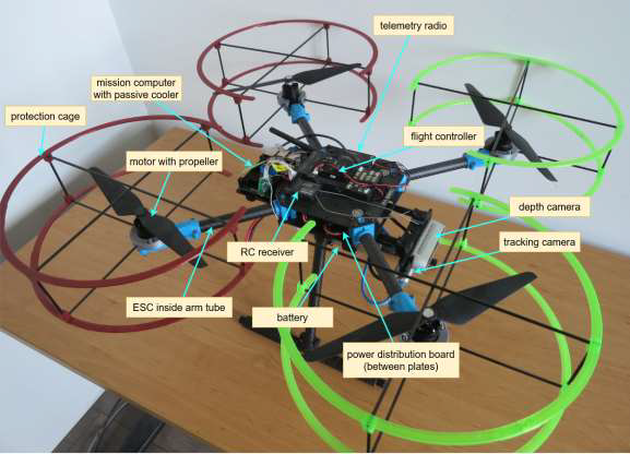
Final Drone
 [Drone with component descriptions]
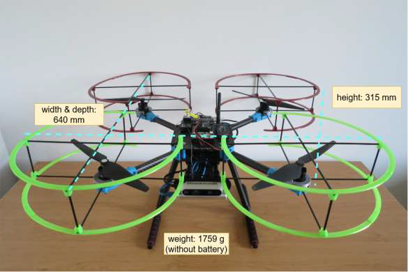 [Basic drone specification]
Software – The Brain Behind It
The software part ran on the Raspberry Pi with ROS2 and Ubuntu Mate 20.04. The Pixhawk used PX4 for basic flight control. The Pi handled mapping, navigation, exploration, and sending commands to the flight controller.
Simulation
I started in Gazebo to test without risking the real drone. Built a URDF model of the drone (with xacro for easy changes), converted it to SDF for Gazebo, and used robot_state_publisher for transforms. RViz showed point clouds, video, and paths. This let me debug navigation and exploration early—much safer and faster than real flights.
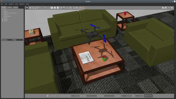 [Drone model in simulated environment]
Build TF tree
To make navigation and mapping work reliably, I had to build and prepare a full TF tree—basically set up all the coordinate frames and how they relate to each other so the different software parts could talk properly.
ROS gives tools to broadcast, listen to, and view transforms. In my case, I defined static transforms for everything fixed on the drone using the URDF model (treating the drone as one rigid piece). The only changing transform was between odom (the odometry reference) and base_link (the drone’s center).
Since the drone’s pose actually came from the tracking camera frame (tracking_cam_frame), not base_link, I had to adjust it: I recalculated the pose using the known static transform between base_link and tracking_cam_frame. This way, the odom-to-base_link transform stayed accurate and the TF tree was ready for the rest of the system to use.
With the tree finalized and broadcasting properly, localization, point cloud alignment, and path planning could all run without frame mismatches.
The depth camera (D435i) gives 3D points relative to its own frame (depth_cam_frame). To use them with the drone’s position, I needed to transform those points to base_link.
I used TF to get the static transformation matrix from depth_cam_frame to base_link. Applying this matrix to each point moved it into the drone’s body frame. This aligned the depth data with the tracking camera’s pose, so RTAB-Map could build a consistent 3D map of the environment around the drone.
These two transformations—adjusting the tracking pose and shifting depth points—made sure localization, navigation, and mapping all worked from the same reliable reference frame.
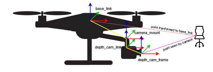 [Transforming the pose of the seen object to the base_link frame]
Video streaming
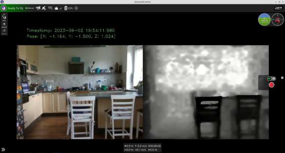
Video streaming was important for monitoring the drone during flights. The stream included three things: RGB camera video, depth map from the depth sensor, and metadata with timestamp and the drone’s current position (X, Y, Z).
Real-time map streaming was not possible because of slow Wi-Fi, especially in places with weak signal. Instead, I focused on streaming the raw camera feeds.
I used GStreamer to create an RTSP server running in a separate thread inside a ROS node. Frames came directly from the RealSense cameras using the librealsense SDK and were converted to OpenCV images. OpenCV combined the RGB and depth frames side by side and added the metadata text. The final frame went to the RTSP server for streaming.
The stream could be viewed on the ground station or in any video player that supports network streams, like VLC.
The delay stayed under 300 ms—I measured it by pointing a camera at the monitor showing the stream, creating an “infinity mirror” effect with visible timestamp differences.
Thanks to hardware H.264 encoding on the Raspberry Pi, the whole process used only about 7% of one CPU core—very efficient for the Pi.
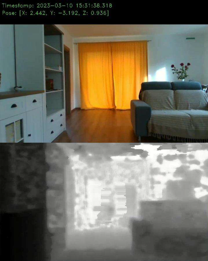 [Video stream from the drone]
3D reconstruction from the depth image
The 3D map was built from depth images coming from the D435i camera. Each depth image is basically a 2D grid where every pixel shows the distance from the camera to whatever is in front of it.
To turn these into a usable 3D map, I used RTAB-Map. It takes the depth image, calculates the 3D coordinates for each point, and creates a point cloud. Then it combines multiple point clouds into one continuous 3D reconstruction of the room or space.
For aligning everything correctly, RTAB-Map relied on odometry from the T265 tracking camera. This gave accurate position and orientation of the depth camera for each frame, so point clouds lined up without big gaps or overlaps.
RTAB-Map also handled localization: using the T265 odometry, it estimated where the drone was inside the growing map. This let the drone know its location for navigation and path planning.
On top of that, it had loop closure detection. When the drone came back to a place it had seen before, RTAB-Map recognized it and corrected any small drift or errors that had built up in the map over time. This kept the final map much more accurate.
In practice, I lowered the mapping update rate during flights to keep the Raspberry Pi from overheating and to save resources, but the results were still solid for indoor rooms.
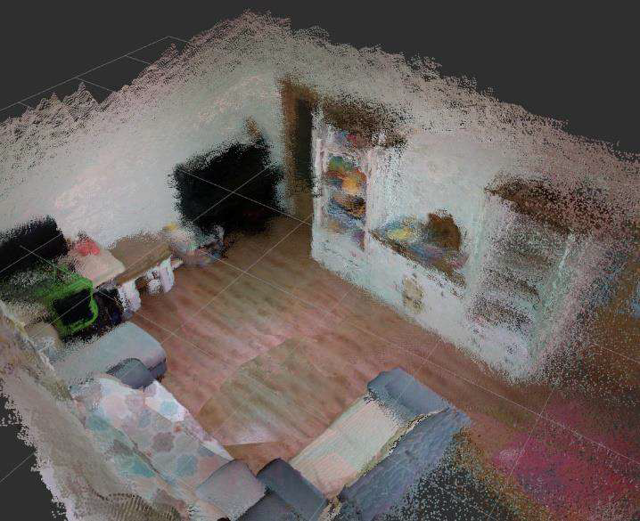 [Point cloud of a room created by RtabMap]
Localization and navigation
Localization and navigation were the core of making the drone autonomous. First, a map of the environment had to exist—either built by flying the drone manually with the RC transmitter while RTAB-Map recorded the point cloud, or by loading a pre-made map into the RTAB-Map database.
For localization, the T265 tracking camera provided real-time visual odometry. It tracked features like edges and corners in the images to estimate the drone’s position and orientation. The built-in IMU added acceleration and rotation data to make this more accurate and stable, especially during quick movements.
The odometry data fed into the Nav2 navigation stack. Nav2 used this to place the drone inside the 3D map from RTAB-Map.
Navigation worked with a 2D costmap: Nav2 projected the 3D point cloud down to a 2D layer at a fixed height above the drone, marking free space and obstacles. This costmap helped both planners:
- Global planner (A* or Dijkstra) took the goal location, current position, and costmap to create an overall path of waypoints, avoiding known obstacles.
- Local planner (Dynamic Window Approach – DWA) adjusted the path in real time based on the global plan and immediate surroundings, handling dynamic changes or small errors.
The path follower turned the local plan into velocity commands. To send these to the drone, I switched the Pixhawk to offboard mode—this let the Raspberry Pi directly control speed and direction instead of the RC transmitter.
Nav2 subscribed to the drone’s odometry, transformed it into the map frame, and used it to keep the drone on track. Everything ran as ROS2 nodes communicating via messages and services—straightforward but required careful tuning for smooth indoor performance.
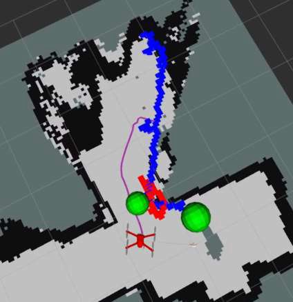
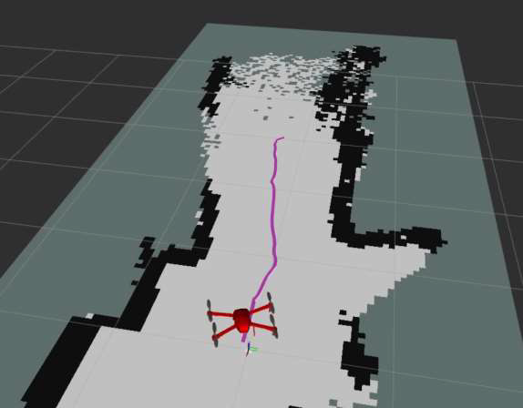 [Navigation and path following using 2D costmap]
Exploration
Exploration combined mapping and navigation to let the drone discover and map new areas on its own, while keeping time and battery use reasonable.
I used the explore_lite ROS package for frontier-based exploration—a common method where the robot heads toward the boundary (frontier) between known and unknown space.
The process started with RTAB-Map building the 3D point cloud map from the depth camera. This map was projected down to a 2D costmap at a fixed height above the drone, so obstacles were clearly marked for planning.
explore_lite then scanned the costmap to find frontiers—edges where explored space meets unexplored. It picked the closest frontier to the drone’s current position, created a goal there, and sent it to the Nav2 stack (the same navigation setup from earlier) to plan and follow a path.
Nav2 handled the actual movement: global planner for the overall route, local planner for avoiding surprises on the way. The drone kept going until enough of the area was covered (based on a simple coverage threshold), or I stopped it manually if needed.
This made the drone truly autonomous indoors—it decided where to go next based on what it hadn’t seen yet, without me constantly guiding it.
 [Exploration progress]
Flight controller
The Pixhawk 6X ran PX4 firmware to handle basic stabilization, motor control, and safety features like low-battery warnings. The main goal was to let the Raspberry Pi take over for autonomous flying.
To do this, I set up an Ethernet connection between the Pi and Pixhawk with static IP addresses on the same network. On the Pi, I edited the Netplan config file and applied the changes. On the Pixhawk, I updated the net.cfg file on the SD card and rebooted. A quick ping test from the Pi confirmed they could talk to each other.
For the actual data exchange, I used micro-ROS. It bridged ROS2 on the Pi to PX4’s uORB messaging system. The micro-ROS agent ran on the Pi, the client on the Pixhawk, communicating over UDP. This let the Pi publish velocity commands and receive telemetry as if it were normal ROS2 topics.
With everything connected, I switched the flight controller to offboard mode. This allowed the Pi to control velocity and direction directly. The process involved:
- Monitoring the drone’s status topic.
- Sending an arm command and waiting for confirmation.
- Switching to offboard mode and waiting again.
- Publishing a continuous heartbeat to keep the mode active.
- Sending velocity setpoints at 50 Hz for smooth control.
A simple state machine in the ROS node handled the sequence step by step. The drone’s current position (from the T265 camera) was fed back so the system could check progress and calculate any needed corrections.
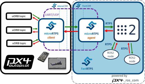 [Relation between the microRTPS client and microRTPS agent]
Ground Station
The ground station was a regular laptop used to monitor the drone and send basic commands during flights. It showed telemetry data like battery level, altitude, speed, and attitude, plus the live video stream.
I mainly used QGroundControl—an open-source app that works on Windows, macOS, and Linux. It’s designed for PX4 autopilots like the one in my Pixhawk, so it handled calibration, parameter tweaks, diagnostics logs, and basic control (arm/disarm, mode changes). It also displayed the RTSP video stream from the drone nicely.
QGroundControl is great for outdoor GPS flights where it shows the drone on a map, but indoors without GPS, that feature wasn’t useful. Still, it was a solid choice for the essentials: watching telemetry, seeing the live RGB/depth video, and having a reliable interface for safety overrides.
The biggest limitation was no real-time point cloud visualization—the data was too heavy for Wi-Fi anyway. I only reviewed the full 3D maps offline after landing, by downloading the RTAB-Map database from the Pi.
For triggering autonomous behaviors, I used a simple SSH client to connect to the Raspberry Pi over Wi-Fi. This let me run commands directly on the mission computer, like starting exploration by calling the ROS2 service /drone/start_exploration or stopping it with /drone/stop_exploration. I chose SSH over sending MAVLink commands from QGroundControl because the Pi was supposed to handle all the high-level logic—it was cleaner to let the user request actions on the Pi, which then sent the right velocity or mode commands to the Pixhawk.
Overall, the setup was basic but effective: QGroundControl for monitoring and video, SSH for starting/stopping autonomy, and manual RC takeover always ready as backup.
 [QGroundControl application with video from a drone]
How I tested it
Tests happened indoors on one floor—usually a room or a couple connected by a corridor. I’d place the drone in the middle, go through the usual checklist: props secure, wiring good, battery connected, everything tight. Power on, boot up, link the ground station and RC transmitter (RC always stayed on for safety). Arm the drone, lift it to about 1 meter with the transmitter, then do a slow full spin so RTAB-Map could scan the immediate surroundings and lock in solid initial localization.
Once hovering stable, I’d SSH into the Raspberry Pi from my laptop and call the ROS2 service to switch to offboard mode. Then trigger exploration with another quick service call. The drone would start creeping toward frontiers, slowly opening up new areas. I watched the live RGB + depth video feed in QGroundControl the whole time and kept my finger on the RC sticks in case it headed somewhere dumb (like straight into a blind corner). It kept going until it had covered most reachable space, then headed back to the starting spot by itself.
For landing, I switched to landing mode—slow controlled descent, soft touchdown, auto-disarm. After that, I downloaded the RTAB-Map database from the Pi and opened the point cloud in RViz offline. The resulting scans weren’t super detailed, but I could clearly recognize room shapes, furniture outlines, doorways, and elevation changes—loop closure helped fix most of the drift, so the maps felt coherent enough to prove the concept worked.
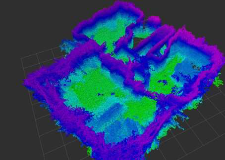 [A point cloud showing the elevation of an indoor environment]
Conclusion
This whole project was mostly about learning, figuring out how to glue existing open-source tools together, debugging endlessly, and making them actually work on real hardware. I didn’t invent much new; I just took pieces like ROS2, RTAB-Map, Nav2, explore_lite, PX4, and micro-ROS and got them playing nice for indoor drone scanning.
The goal was simple: build a drone that scans indoor spaces with a depth camera and eventually does it autonomously. I broke it into steps: assemble the hardware, prove manual 3D scanning, add navigation in known maps, enable self-exploration of unknown areas, and set up a basic ground station to monitor and trigger stuff.
Stuff that could be better: 2D navigation feels limiting in real 3D rooms (odd paths sometimes), no practical live point cloud over Wi-Fi (data too heavy), flights max out around 15 minutes, and the drone’s size makes tight spaces awkward.
But honestly, seeing it fly around mapping a room on its own and coming back with a recognizable point cloud was satisfying. It proved you can do decent indoor 3D scanning with affordable gear and free tools—a solid base for mapping, inspection, or similar tasks.