
This post explains how the fleet simulator actually works: how robot Docker containers are created, how they communicate with the Gazebo server (also running in a container), and how multiple robots can perceive each other by sharing the same simulated world. The goal is to demonstrate that two completely isolated robot backends can still interact through a single Gazebo instance, exactly as they would in the real world.
Principle
In a standard setup, Gazebo and the ROS master usually run on the same machine, which simplifies communication significantly. In my approach, everything runs in its own Docker container. Each robot has its own isolated ROS environment with its own ROS master, while Gazebo runs as a shared simulation server. All containers communicate through a dedicated Docker network defined in docker-compose.yaml.
1
2
3
4
5
6
networks:
  fleet_sim_network:
    ipam:
      driver: default
      config:
        - subnet: "192.168.40.0/24"
Each container is assigned a static IP address from this network. For simplicity, I created two robot containers called robot_01 and robot_02. The first one gets the IP address 192.168.40.101, the second 192.168.40.102. The Gazebo simulation server runs in a container called sim_server with IP 192.168.40.100.
This setup closely mirrors a real deployment scenario, where each robot has its own computer and IP address, and the simulation server acts as a shared environment.
Why Gazebo Does Not Talk to ROS Directly
In the standard Gazebo–ROS integration, Gazebo loads plugins that interact with the simulated world and communicate with ROS through a ros::NodeHandle. This works well for a single robot, but it breaks down when multiple robots with separate ROS masters are involved.
The reason is a fundamental limitation of ROS: it uses a global singleton node handle created by ros::init. Every ROS node created in the same process refers to the same internal global state, which means it is not possible for a single Gazebo process to connect to multiple ROS masters at different addresses. Since all Gazebo plugins are loaded into the same process, they would all end up communicating with the same ROS master.
For this reason, Gazebo in this architecture does not communicate with ROS directly.
Instead, Gazebo is treated as a pure simulation server, and communication happens through Gazebo’s native transport layer, which uses a pub/sub mechanism similar to ROS but is implemented with Protocol Buffers and operates over TCP/IP.
Robot Side
Each robot container runs a standard ROS environment with its own ROS master, navigation stack, and control nodes. From the ROS point of view, the robot behaves exactly like a real physical robot: it publishes odometry, TF, and laser scans, and it subscribes to /cmd_vel for motion commands. The hardware interface is replaced by a simulation bridge node implemented in simulation.cpp.
This node connects to the Gazebo simulation server using the address provided by the GAZEBO_MASTER_URI environment variable. The Gazebo transport layer uses this value to discover the server, while the GAZEBO_IP and GAZEBO_HOSTNAME variables define the network address under which the robot container advertises its own transport endpoints.
Once connected, the node spawns the robot model in Gazebo by publishing a gazebo::msgs::Factory message to the ~/factory topic. The robot description is taken from the /robot_description ROS parameter, and the initial pose is read from ROS parameters as well, allowing each robot to spawn at a different position.
After spawning, the node establishes all communication channels:
- it subscribes to Gazebo transport topics for odometry, wheel transforms, and laser scans
- it publishes velocity commands to Gazebo using a model-specific topic
- it republishes Gazebo data into ROS topics and TF frames
Because this translation happens entirely inside the robot container, each robot’s ROS graph remains fully isolated. Topic names such as /cmd_vel, /scan, and /odom are identical across robots, but they never collide because they belong to different ROS masters. From the navigation stack’s perspective, there is no difference between simulation and real hardware.
Gazebo Side
The Gazebo container runs a single simulation server that hosts the shared world and all robot models. It does not run ROS. Instead, it exposes robot state and sensors exclusively through Gazebo’s native transport layer.
When a robot is spawned, Gazebo loads the shared library librobot_plugin.so, which is compiled from robot_plugin.cpp. This plugin is attached to the robot model and is responsible for all simulation-side behavior. It is based on the structure of the standard gazebo_ros_diff_drive and gazebo_ros_laser plugins, but all ROS communication has been removed.
The plugin performs the following tasks:
- it subscribes to a Gazebo
cmd_veltopic specific to the model - it applies differential-drive kinematics directly to wheel joints
- it publishes odometry pose and twist
- it publishes wheel-relative poses for TF reconstruction on the robot side
- it subscribes to the native Gazebo laser topic and republishes it under a model-specific topic
All topics are namespaced by the model name, which allows multiple identical robots to run in the same world without interference. For example, each robot publishes its odometry on /<robot_id>/odometry and listens for commands on /<robot_id>/cmd_vel.
Because all robot plugins run inside the same Gazebo world, they naturally interact through physics and sensors. Laser scans, collisions, and occlusions are handled entirely by the simulation engine. From Gazebo’s perspective, there is no concept of robots or fleets—only multiple models interacting in one world.
This clean separation between Gazebo (physics and sensors) and ROS (control and autonomy) is what allows the system to scale while keeping each robot backend simple and realistic.
Bring It to Life
Bringing the system up is a structured process: the simulation server is started first, and robot backends are launched afterward. Each component runs in its own container, but all of them connect to the same Gazebo world.
Building and Starting Containers
To simplify the workflow, I use a small Makefile that wraps docker compose commands. It provides short targets for building and starting individual services without repeating long commands.
After building the images, all containers are started. At this stage, the containers only provide isolated runtime environments; no ROS nodes or Gazebo processes are running yet.
Attaching to Running Containers
Once the containers are up, I attach to them from separate terminals. Each terminal corresponds to one running container.
Terminal 1 (robot_01):
1
make attach-robot ROBOT=robot_01
Terminal 2 (robot_02):
1
make attach-robot ROBOT=robot_02
Terminal 3 (Gazebo simulation server):
1
make attach-sim
Each container runs a tmux session, making it easy to start, stop, and restart processes during development.
The robot source code is shared between all robot containers, and the build output is also shared. This means that compiling ROS nodes in one robot container immediately makes the binaries available to all other robot containers. The Gazebo container, on the other hand, has its own separate source tree and build artifacts, which are used only to build and load the simulation plugins.
Build robot backend
Terminal 1 (robot_01):
1
2
cd catkin_ws
catkin build
Build gazebo robot_plugin
Terminal 3 (Gazebo simulation server):
1
2
3
4
5
cd sim_server
mkdir build
cd build
cmake ..
make -j$(nproc)
Starting the Simulation Server
Gazebo must be started first so the world is available before robots attempt to connect to it. Inside the sim_server container:
1
gazebo --verbose worlds/arena.world
This launches the Gazebo server and loads the world, but no robots are present yet.
Launching the Robots
Each robot is started independently from its own container:
1
roslaunch robot_bringup start.launch start_mode:=localization
The launch process is identical for both robots. The robot identity is derived from the container name and passed through launch arguments and ROS parameters. Based on this ID, the correct spawn position is selected and provided to the simulation node.
During startup, the following happens:
- The simulation bridge node connects to the Gazebo server and spawns the robot model at the configured position.
- The robot state publisher starts and begins publishing the TF tree.
- Localization, navigation, and RViz are launched with an initial pose matching the spawn location.
Two Robots, One Simulation
After both robots are running, the Gazebo world contains two mobile platforms. Each robot opens its own RViz instance, showing its local view of the environment.
Because both robots share the same simulation world, they naturally perceive each other through their sensors. Laser scans include the other robot as a moving obstacle, and all interactions are handled entirely by the simulation engine. The robot backends remain isolated, while Gazebo acts as the only shared point of interaction.
At this point, the fleet simulator is fully running: multiple robot backends, a single shared Gazebo world, and a clean separation between simulation and robot autonomy.
Screenshots
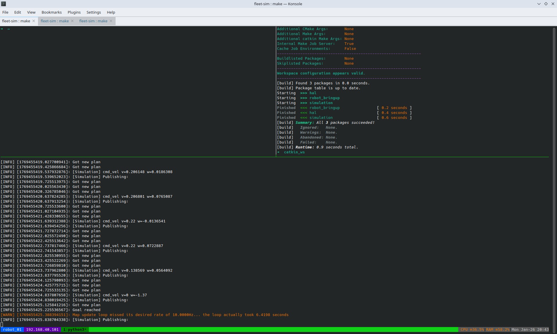
robot_01 tmux terminal
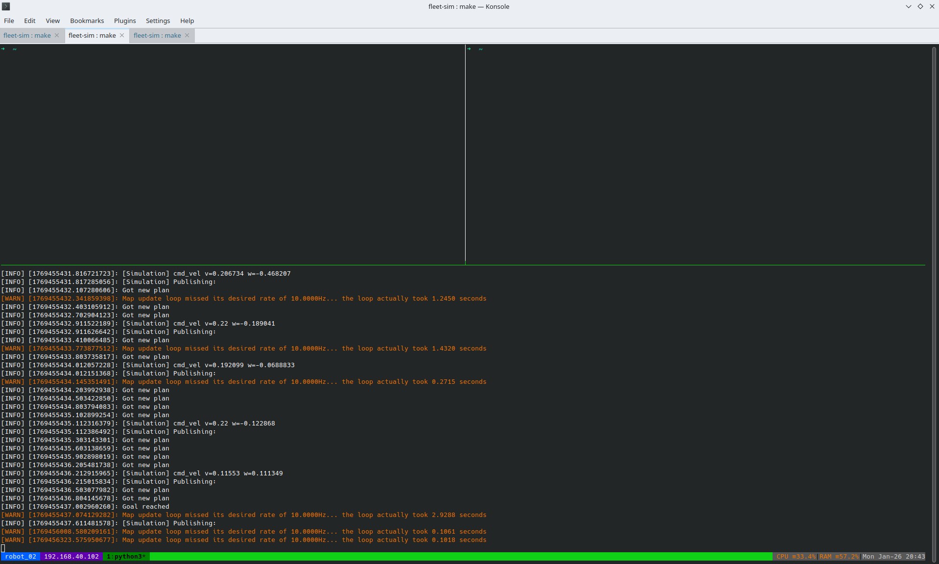
robot_02 tmux terminal
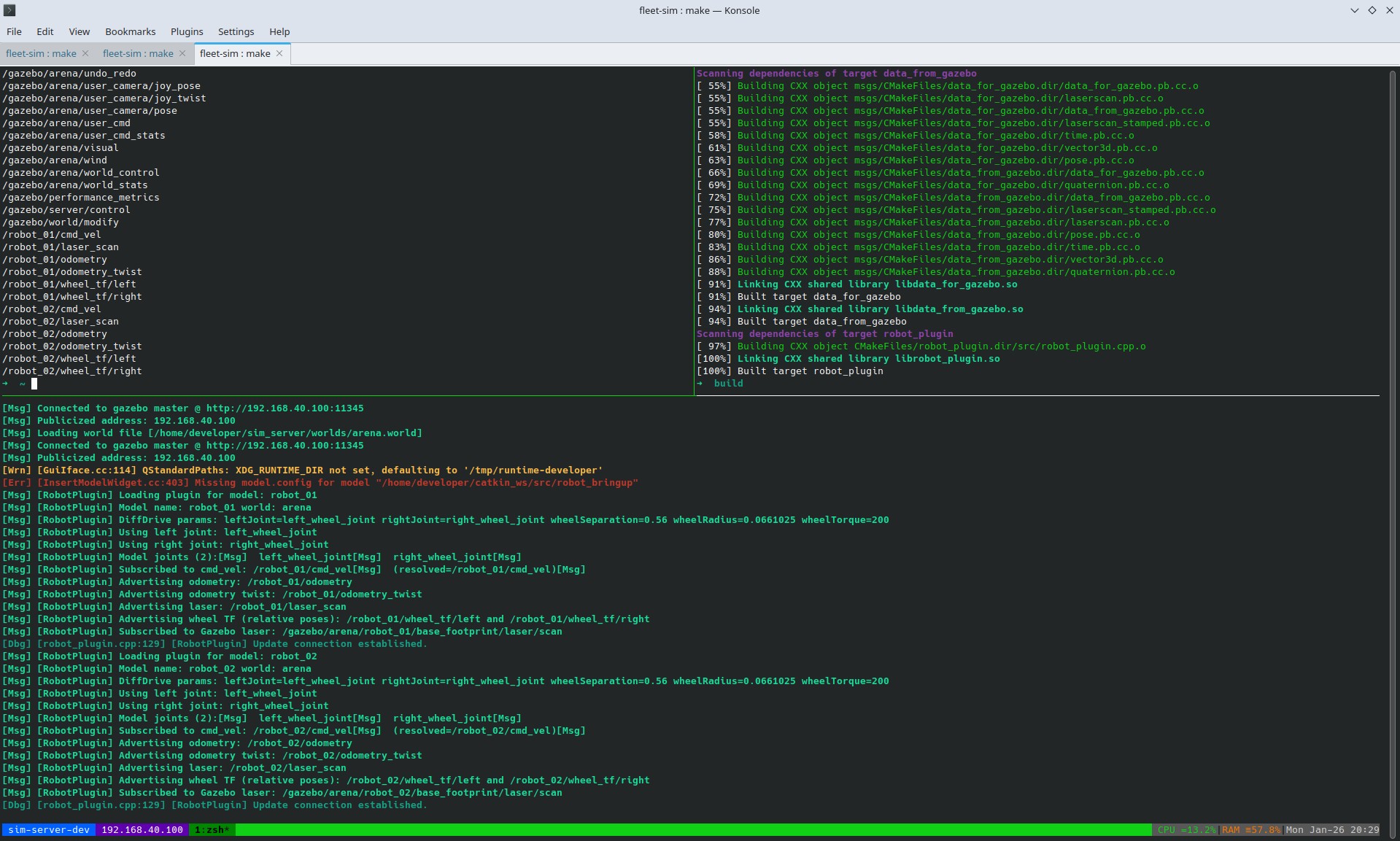
Gazebo tmux terminal
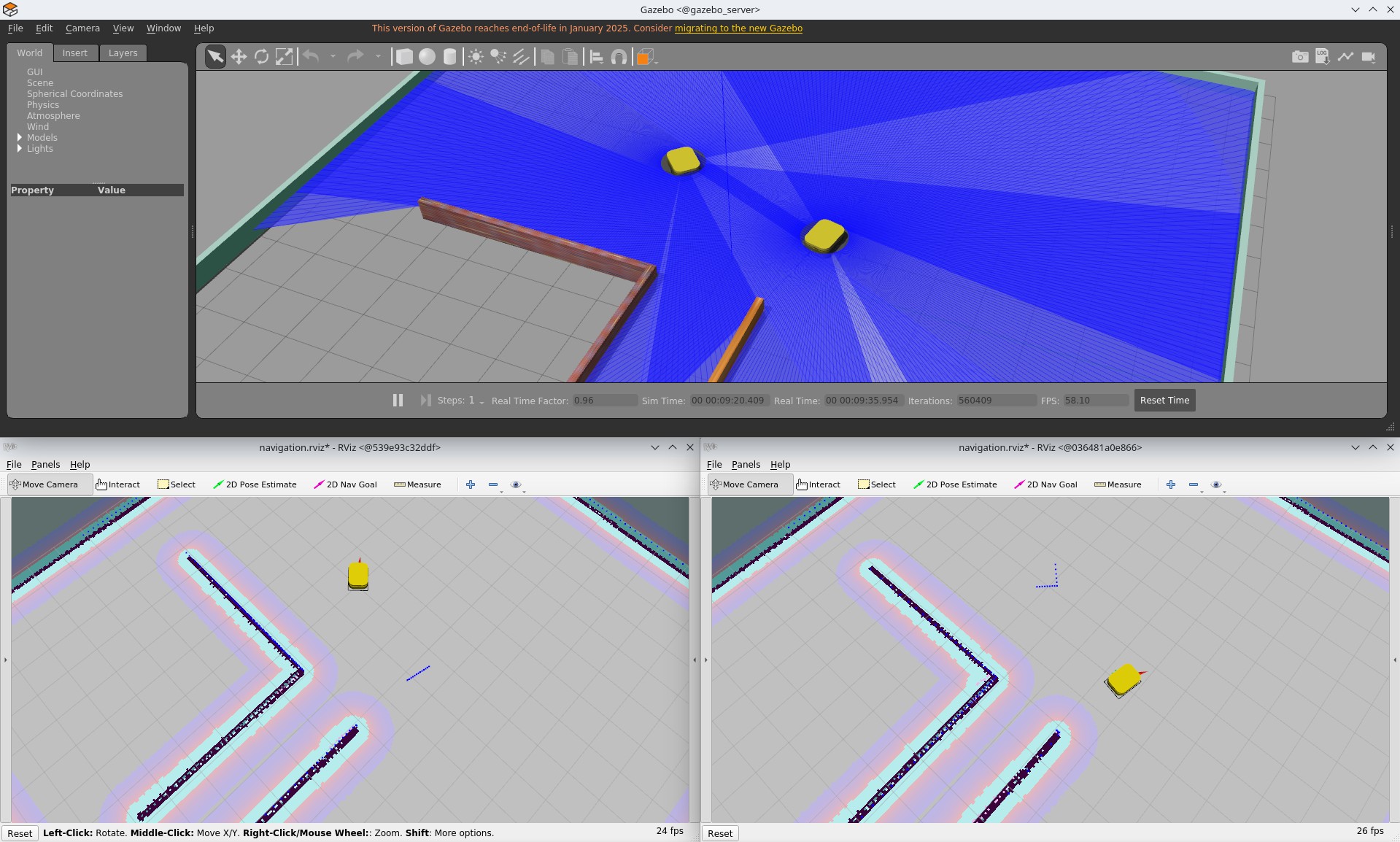
Gazebo and two RViz apps
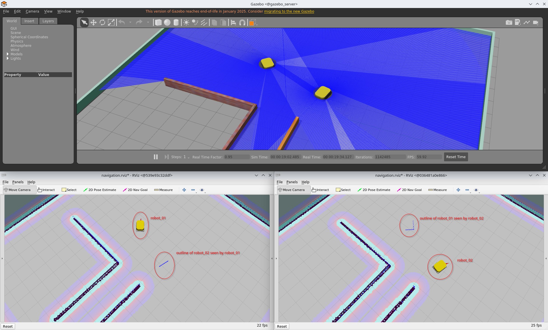
Gazebo and two RViz apps with description
Next Steps
This setup serves as a proof of concept that multiple isolated robot backends can interact through a single shared simulation world. It shows that realistic multi-robot interaction is possible without sharing a ROS master, while keeping each robot’s software stack simple and self-contained.
The next step is to introduce a fleet management layer. Instead of controlling robots individually, a central system could coordinate their motion according to a global objective. This includes challenges such as efficient task allocation in a warehouse-like environment, avoiding collisions in narrow passages, preventing congestion at bottlenecks, and managing charging strategies to keep the fleet operational over time. At this level, robots become part of a coordinated system rather than isolated entities.
Communication between robots and the fleet manager would occur through rosbridge nodes, providing a clean API for each robot. This allows the fleet manager to operate externally without breaking the isolation between robot backends.
Another step is the development of a fleet-level visualization and control tool. While each robot currently has its own RViz instance, this does not scale well beyond a few robots. A dedicated interface could display all robots in the environment simultaneously, showing their states, assigned tasks, and planned trajectories. It could also provide controls for the entire fleet or for individual robots, giving a clear operational overview.
Finally, although this project uses ROS 1, future work should migrate to ROS 2. ROS 2 provides improved communication primitives, better multi-robot support, and a more natural fit for distributed systems. Reimplementing this setup in ROS 2 would simplify parts of the design while making the simulator closer to modern frameworks.
This project lays the foundation. The next steps focus on scaling coordination, observability, and control from individual robots to a full fleet.